Introduction to Computer Graphics and Java Programming for Artists


School of the Museum of Fine Arts ::: Continuing Education

George Aroush, instructor


Lecture Eight -- 3D Graphics -- Part I


Readings

  1. The handouts named:
  2. Sample Programs in Batch Eight:
  3. Graphics Book


Exercises

    Do before our next lecture

  1. Create your own three dimensional object as a set of vertices and edges in arrays, as in CubeOne.java, CubeTwo.java and CubeThree.java. Display the object, using either the code in those demo programs or something you've developed yourself. As a first step, you might want to display just the vertices; after those look okay, get the edges to show.
  2. Modify CubeThree.java or your own three dimensional display program to make an object (could be the cube) move in a very different way than the bouncing around in CubeThree.java. Suggestions:
    a) a curved or circular path, based on sines and cosines,
    b) a random or partially random path,
    c) zooms toward the viewer from distant, randomly selected locations,
    d) bouncing off of moving walls,
    e) something of your own idea.

Back to the top of this page. Back to main Index


Three Dimensional Graphics: Part 1

Notes on 3D

Three dimensional objects are defined in computer graphics as collections of points or vertices, either connected by edges or grouped together in polygonal faces. Displays of edges are called wire-frame displays, are relatively simple to do and are fast to display, rotate, move, etc. Filled-in faces take more time, are a little more difficult to implement, but can look much more realistic. This hand-out will focus on wire-frame displays. Later we well look at filled 3D objects.

3D Coordinates System

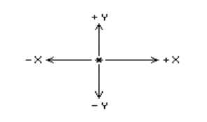
3D graphics uses three dimensional coordinates X, Y, and Z-axes. The X and Y axes are the two-dimensional ones we are already used to. The Z axis is perpendicular to them. In the figure below, the X and Y axes are labeled, and the Z axis passes through the paper, where the ( * ) is:

wpe3.jpg (3031 bytes)

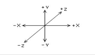
A perspective view of the Z axis is shown in the figure below:

wpe4.jpg (3883 bytes)


The viewer is considered to be a single eyed, whose eye is located at the origin -- where X, Y, and Z all equal 0. We will be using what is known as a left-handed coordinate system -- in which:

X gets larger to the right,
Y gets larger going up,
Z gets larger going to the front (into the paper).

This means that negative Z coordinates are behind the viewer, positive Z coordinates are to the front of the viewer. A point at (50, 60, 70) would be 50 pixels to the right, 60 pixels up and 70 pixels forward, (into the paper.) A point at (20, -15, -90) would be 20 pixels to the right, 15 pixels down and 90 pixels behind the eye (that is behind us.)

Projection

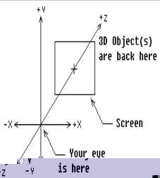
The major problem of wire-frame 3D is getting an object in 3D space to fit, that is to display, on a 2D screen -- how does one project a solid object onto a plane? Think of the viewer as looking through a window located some distance down the Z axis, that is into the paper, right in front of us. This window is the screen, which coincides with the actual video screen a real viewer will look at. The Z-axis passes through the center of the screen. The edges of the screen are paralleled to the X and Y-axes. Think of an object in the 3D space on the other side of the screen from the viewer. That is, the eye is in front of the screen and the screen is in front the object.

wpe6.jpg (6180 bytes)


"Light-rays" travel form the vertices of the object, through the screen and to the viewer's eye. If we could see the light rays piercing the screen, we could mark those places on the screen with spots. If we connect these spots with lines in the correct order, that is in the order that we connected them when we define the shape, we would have a nice perspective drawing of the object. Every 3D program needs to have a projection function. This function requires the X, Y, and Z-coordinates of each point and the distance of the screen from the viewer. The results are placed in another set of X and Y arrays, which are used for the display. The secret of projection is based on the obvious fact that objects appear smaller when they are farther away and larger when they are closer. It would seem that dividing the X and Y-coordinates of the object by the Z-coordinate in some way would make the resulting projection smaller when the Z is large (the object is far away) and make them larger when the Z is small (the object is nearby.) The resulting function works as follows:

projected_x = x * screen_distance / z
projected_y = y * screen_distance / z 

for each point. Fortunately, when we project a straight line, the projection is also a straight line. So we only need to project the end points and connect them with a straight line.

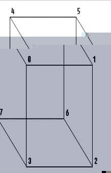
The examples programs all work with a cube, because its a common form, and it is very easy to figure out its X, Y, and Z-coordinates. It has eight corners or vertices, but has 12 edges. This is a little more difficult than drawing 2D outline -- we just can't connect the points in order. Instead, we have to tell the program the order to connect them. We can think of the vertices as being numbered form 0 to 7 -- they are stored in arrays from coord[0][X] to coord[7][X], coord[0][Y] to coord[7][Y], etc. Note that X and Y are pre-defined like:

final int X = 0;
final int Y = 1;

An array of edges should have two numbers, each representing the index of a vertex. On the cube below, the 12 edges are:

0-1        1-2         2-3         3-0
0-4        1-5         2-6         3-7
4-5        5-6         6-7         7-4

wpeA9.jpg (6622 bytes)

Probably (this is true in most cases) the hardest part of doing 3D graphics is figuring out how to connect the edges.

Movement

The three transformations of 3D graphics are translation (movement), scaling, and rotation. We will deal only with movement in this lecture. To move an object, create a three element array trans[], for the amount to move along the X, Y and Z axes. This array and the coordinate arrays are trans[] array are each added to the corresponding X, Y and Z-coordinate for each vertex in coord[][]. When moving 3D objects around, it is easy to go off the screen with the projection. In particular, if the object gets too close to the viewer. Also there is a danger of having Z coordinates equal to zero. Since projection requires dividing the screen distance by the Z-coordinate, this could result in a termination of the program caused by a "division by zero" error. We must always make sure that a vertex is in a safe location before projection. In the demo programs, the values in the coord[] arrays are chosen and kept in limits so that they will always have 2 coordinates greater than 0. So no test is necessary.


Back to the top of this page. Back to main Index


Sample Programs -- Batch Eight

CubeOne.java

/*
 *  Program:    CubeOne.java
 *  Purpose:    3D Demo
 *  Author:     George Aroush
 *  Date:       1/1/1998
 *  Change Log: None
 *
 *  Full description of Program:
 *      Projects and displays vertices of stationary cube
 */

import java.applet.*;
import java.awt.*;

public class CubeOne extends Applet
{
    final int   NP = 8;     /* number of points */
    final int   CX = 320;   /* center of screen */
    final int   CY = 240;
    final int   X = 0;      /* the x, y, and z part of the array */
    final int   Y = 1;
    final int   Z = 2;
	
    public void paint(Graphics g)
    {
        /* Coordinates of cube. This array holds the shape that we want to define in a 3D space */
        float	coord[][] = {{75, 75, 325}, {75, -75, 325}, {-75, -75, 325}, {-75, 75, 325},
                             {75, 75, 475}, {75, -75, 475}, {-75, -75, 475}, {-75, 75, 475}};
        int     proj[][] = new int[NP][2];   /* This array will hold the output 3D shape */
        int     i;                           /* in a 2D form so that we can display it. */
        float   sd = 300.0f;        /* The screen distance */


        /* Project cube on screen, & plot its vertices
         *
         * Project() needs to know the following:
         *
         *	coord --> The array holding the defined 3D shape data 
         *	proj ---> an array in which the 2D shape will be stored in
         *	NP -----> number of points in the array "coord"
         *	sd -----> how far is the screen form the viewer
         */

        Project(coord, proj, NP, sd);		/* calculates where each vertex will be on the 2D screen */

            /* Draw the vertex on the screen. We use the fillOval() */
            /* method to make the vertex larger so we can see them. */
        for (i = 0; i < NP; i++)
            g.fillOval(proj[i][X], proj[i][Y], 5, 5);
    }

    /*
     *	void	Project(coord, proj, np, sd)
     *	
     *	Projects coordinate array onto screen at given screen distance storing 
     *	result as x and y coordinates in proj[][2] array
     */
    void	Project(float coord[][], int proj[][], int np, float sd)
    {
        int	i, j;

        for (i = 0; i < np; i++)
        {
            proj[i][X] = CX + (int) (coord[i][X] * sd / coord[i][Z]);
            proj[i][Y] = CY + (int) (coord[i][Y] * sd / coord[i][Z]);
        }
    }
}

CubeOne.html

<html>
<head>
<title>CubeOne</title>
</head>
<body>
    <hr>
    <applet code=CubeOne width=640 height=480></applet>
    <hr>
</body>
</html>

CubeTwo.java

/*
 *  Program:    CubeTwo.java
 *  Purpose:    3D Movement Demo
 *  Author:     George Aroush
 *  Date:       1/1/1998
 *  Change Log: None
 *
 *  Full description of Program:
 *      Displays and "bounces" a cube on the screen in a 3D space. 
 *      (See week 3's hand-out(s) and demos if you forget how the 
 *      bounce program works.)
 */

import java.applet.*;
import java.awt.*;

public class CubeTwo extends Applet
{
    final int   NP = 8;     /* number of points */
    final int   CX = 320;   /* center of screen */
    final int   CY = 240;
    final int   X = 0;      /* the x, y, and z part of the array */
    final int   Y = 1;
    final int   Z = 2;
	
    public void paint(Graphics g)
    {
        /* Coordinates of cube. This array holds the shape that we want to define in a 3D space */
        float	coord[][] = {{75, 75, 325}, {75, -75, 325}, {-75, -75, 325}, {-75, 75, 325},
                             {75, 75, 475}, {75, -75, 475}, {-75, -75, 475}, {-75, 75, 475}};
        float   trans[] = {10, 10, 10};     /* velocity -- x, y, and z */

            /* Minimum & maximum x, y, & z values for vertex 0 (coord[0][0]) */
        float   limits[][] = {{-307, 307}, {-261, 261}, {300, 1111}};

            /* Holds the x & y points that are the result of projection */
        int		proj[][] = new int[NP][2];

        float   sd = 300;
        int     i, j;


            /* move cube, project it on screen, and display its vertices */
        for (j = 0; j < 2000; j++)
        {
            /* Translate cube on screen, moving it to a new place
             *
             * Translate() needs to know the followings:
             *
             *	coord --> an array holding the defined 3D shape data 
             *	trans --> an array holding the x, y, & z movements
             *	NP -----> number of points in the array "coord"
             */
            Translate(coord, trans, NP);

                /* Test vertex 0 & reverse direction if it has crossed a limit.  Note that vertex 0 */
                /* consists of x, y, & z, so our loop will loop three times for one vertex, testing */
                /* x, y, & z one by one in the if_() statement in the for_() loop. */
            for (i = X; i <= Z; i++)    /* "same as:" for (i = 0; i <= 2; i++) */
            {
                if (coord[0][i] < limits[i][0] || coord[0][i] > limits[i][1])
                    trans[i] *= -1.0;       /* reverse direction */
            }

            Project(coord, proj, NP, sd);   /*calculates where each vertex will be on the 2D screen */

            g.clearRect(0, 0, 640, 480);

            for (i = 0; i < NP; i++)        /* Project cube on screen, & plot its vertices */
                g.fillOval(proj[i][X], proj[i][Y], 5, 5);

            Delay(60);
        }
    }


    /*
     *	void	Project(coord, proj, np, sd)
     *
     *	Projects coordinate array onto screen at given screen distance storing 
     *	result as x and y coordinates in proj[][2] array
     */
    void	Project(float coord[][], int proj[][], int np, float sd)
    {
        int     i;

        for (i = 0; i < np; i++)
        {
            proj[i][X] = CX + (int) (coord[i][X] * sd / coord[i][Z]);
            proj[i][Y] = CY + (int) (coord[i][Y] * sd / coord[i][Z]);
        }
    }


    /*
     *	void	Translate(coord, trans, np)
     *	
     *	Add three values of trans[3] to each vertex in coord[][3] thus moving vertices along all three axes
     */
    void	Translate(float coord[][], float trans[], int np)
    {
        int	i, j;

        for (i = 0; i < np; i++)    /* loop in the array */
        {
            for (j = 0; j < 3; j++)     /* loop in the vertex */
                coord[i][j] += trans[j];
        }
    }


    /*
     *  void    Delay()
     *
     *  Simply pauses for some time
     */
    public void Delay(int delayTime)
    {
        try
        {
            Thread.sleep(delayTime);    /* call Java's sleep method */
        }
        catch (InterruptedException e)
        {
            /* when the sleep() call above is over, Java will */
            /* be interuppted and we fall into this block of code */
            /* because our intention is simply slow down things */
            /* wed do nothing in our exception code and just get out */
        }
    }
}

CubeTwo.html

<html>
<head>
<title>CubeTwo</title>
</head>
<body>
    <hr>
    <applet code=CubeTwo width=640 height=480></applet>
    <hr>
</body>
</html>

CubeThree.java

/*
 *  Program:    CubeThree.java
 *  Purpose:    3D Movement Demo
 *  Author:     George Aroush
 *  Date:       1/1/1998
 *  Change Log: None
 *
 *  Full description of Program:
 *      Displays and "bounces" a cube on the screen in a 3D space, 
 *      how to display a wire-frame 3D shape, connecting its vertex 
 *      by a line segments
 */

import java.applet.*;
import java.awt.*;

public class CubeThree extends Applet
{
    final int   NP = 8;     /* number of points */
    final int   NE = 12;    /* number of edges */
    final int   CX = 320;   /* center of screen */
    final int   CY = 240;
    final int   MAXX = 512; /* used to check if a line is on the screen */
    final int   MAXY = 342;
    final int   X = 0;      /* the x, y, and z part of the array */
    final int   Y = 1;
    final int   Z = 2;
	
    public void paint(Graphics g)
    {
            /* Coordinates of cube. This array holds the shape that we want to define in a 3D space */
        float	coord[][] = {{75, 75, 325}, {75, -75, 325}, {-75, -75, 325}, {-75, 75, 325},
                             {75, 75, 475}, {75, -75, 475}, {-75, -75, 475}, {-75, 75, 475}};
    	    /* index numbers of coordinates for endpoints of edges */
        int     edge[][] = {{0, 1}, {1, 2}, {2, 3}, {3, 0},
                            {0, 4}, {1, 5}, {2, 6}, {3, 7},
                            {4, 5}, {5, 6}, {6, 7}, {7, 4}};

            /* velocity -- x, y, and z */
        float   trans[] = {10, 10, 10};

            /* Minimum & maximum x, y, & z values for vertex 0 (coord[0][0]) */
        float   limits[][] = {{-400, 400}, {-400, 400}, {300, 1111}};

            /* Holds the x & y points that are the result of projection */
        int		proj[][] = new int[NP][2];

        float   sd = 300;
        int     i, j;


            /* move cube, project it on screen, and display its vertices */
        for (j = 0; j < 2000; j++)
        {
            /* Translate cube on screen, moving it to a new place
             *
             * Translate() needs to know the followings:
             *
             *	coord --> an array holding the defined 3D shape data 
             *	trans --> an array holding the x, y, & z movements
             *	NP -----> number of points in the array "coord"
             */
            Translate(coord, trans, NP);

                /* Test vertex 0 & reverse direction if it has crossed a limit.  Note that vertex 0 */
                /* consists of x, y, & z, so our loop will loop three times for one vertex, testing */
                /* x, y, & z one by one in the if_() statement in the for_() loop. */
            for (i = X; i <= Z; i++)    /* "same as:" for (i = 0; i <= 2; i++) */
            {
                if (coord[0][i] < limits[i][0] || coord[0][i] > limits[i][1])
                    trans[i] *= -1.0;       /* reverse direction */
            }

            Project(coord, proj, NP, sd);   /*calculates where each vertex will be on the 2D screen */

            g.clearRect(0, 0, 640, 480);

            /*
             * Displays a wire-frame of object.
             *
             * Display() needs to know the followings:
             *
             *	proj ---> an array in which the 2D shape are stored
             *	edge----> an array dells display() how to connect the shape
             *	sd -----> number of points in the array "coord"
             */

            Display(proj, edge, NE, g);

            Delay(60);
        }
    }


    /*
     *	void	Project(coord, proj, np, sd)
     *
     *	Projects coordinate array onto screen at given screen distance storing 
     *	result as x and y coordinates in proj[][2] array
     */
    void	Project(float coord[][], int proj[][], int np, float sd)
    {
        int     i;

        for (i = 0; i < np; i++)
        {
            proj[i][X] = CX + (int) (coord[i][X] * sd / coord[i][Z]);
            proj[i][Y] = CY + (int) (coord[i][Y] * sd / coord[i][Z]);
        }
    }


    /*
     *	void	Translate(coord, trans, np)
     *	
     *	Add three values of trans[3] to each vertex in coord[][3] thus moving vertices along all three axes
     */
    void	Translate(float coord[][], float trans[], int np)
    {
        int	i, j;

        for (i = 0; i < np; i++)    /* loop in the array */
        {
            for (j = 0; j < 3; j++)     /* loop in the vertex */
                coord[i][j] += trans[j];
        }
    }


    /*
     *	void	Display(proj, edge, ne)
     *	
     *	Displays wire frame of object.  Uses values in edge[][2] to find starting and 
     *	ending vertex for each edge
     */
    void	Display(int proj[][], int edge[][], int ne, Graphics g)
    {
        int     e;
        int     s, f;
        int     x1, y1, x2, y2;

        for (e = 0; e < ne; e++)
        {
            s = edge[e][0];     /* s -- is the starting vertex */
            f = edge[e][1];     /* f -- is the ending vertex */

            x1 = proj[s][X];    /* stating point of a line */
            y1 = proj[s][Y];

            x2 = proj[f][X];    /* ending point of a line */
            y2 = proj[f][Y];

                /* make sure the the line is on the screen */
            if (x1 >= 0 && x1 < MAXX && y1 >= 0 && y1 < MAXY && 
                x2 >= 0 && x2 < MAXX && y2 >= 0 && y2 < MAXY)
            {
                g.drawLine(x1, y1, x2, y2);
            }
        }  
    }


    /*
     *  void    Delay()
     *
     *  Simply pauses for some time
     */
    public void Delay(int delayTime)
    {
        try
        {
            Thread.sleep(delayTime);    /* call Java's sleep method */
        }
        catch (InterruptedException e)
        {
            /* when the sleep() call above is over, Java will */
            /* be interuppted and we fall into this block of code */
            /* because our intention is simply slow down things */
            /* wed do nothing in our exception code and just get out */
        }
    }
}

CubeThree.html

<html>
<head>
<title>CubeTwo</title>
</head>
<body>
    <hr>
    <applet code=CubeThree width=640 height=480></applet>
    <hr>
</body>
</html>

Back to the top of this page. Back to main Index.